
Ennex in Digital Fabrication
Copyright © 2003, 2020, Ennex. All rights reserved.
Summary:
In the 1990s, a number of technologies were developed that used digital data and raw materials to make arbitrary, three-dimensional, solid objects. Known at the time mostly as “rapid prototyping,” these technologies had far more potential than that name suggested. Marshall Burns wrote the first major book on this subject, calling it Automated Fabrication, and started Ennex Fabrication Technologies to promote a vision of “digital fabricators” setting people free from the confines of mass manufacturing. Burns was invited to speak at conferences from Japan to Nigeria and consulted to IBM, Dow Chemical, the US Navy, and numerous other clients on how to use or develop “fabbers” for manufacturing, medical, modeling, and other applications. Twenty years later, the technology attracted popular interest in what is now more commonly known as “3D printing.”
Fabbing the Future
by Marshall Burns
In October 1990, when I was nearing completion of my PhD in physics at the University of Texas at Austin, I went to a workshop for entrepreneurs sponsored by the Austin Technology Incubator. The program included video presentations on some of the incubator’s tenant businesses. One of those companies was DTM Corporation, whose video showed a machine that used a laser beam and plastic powder to turn a computer design into a solid object. I was dumbfounded. “Could this be real?” I asked myself. I spent the next three weeks in the library reading everything I could get my hands on about what I discovered was a whole field of academic and entrepreneurial research and development. I found out that DTM’s technology was only one of more than a dozen processes under development around the world for achieving the same objective, and that a company by the name of 3D Systems had sold over a hundred of a liquid-based machine to the likes of General Motors, Kodak and Apple Computer.
The technology went by several names — “desktop manufacturing” (the source of the DTM name), “solid freeform fabrication,” and the one that stuck the most through the ’90s, “rapid prototyping.” I never liked that name because, in my view, this technology would ultimately be about making whatever someone wants, not just prototypes. After being involved in the field for several years, I found that the term “automated fabrication,” and later “digital fabrication,” seemed to better encompass the purpose and potential of the technology.
After completing my PhD in early 1991, I spent four months driving around the U.S. and Canada meeting as many of the inventors, entrepreneurs, and users of digital fabricators as I could find. Convinced more than ever that what I was seeing was the beginnings of a blockbuster industry, I settled down in Los Angeles and set up Ennex Fabrication Technologies as a sole proprietorship. The company was conceived with two lines of business:
 The Expertise Line offered educational and consulting services related to digital fabrication. The most important product was the book, Automated Fabrication—Improving Productivity in Manufacturing, published by Prentice Hall in 1993. That book led to invitations to speak at conferences in Europe, Japan, and even Africa. I also taught courses on automated fabrication at the University of Southern California (USC) and the California Institute of Technology (Caltech). Major consulting projects were conducted for Dow Chemical, Rockwell International, Bristol-Myers Squibb, Hüls AG (Germany), the US Navy, and many other companies and organizations, large and small.
 The Technology Line created new fabrication technologies to be licensed or developed directly for commercial use. The most important project in this line was on Offset Fabbing, a process that formed and laminated successive patterns of an adhesive film material to build up a solid object. Three patents were issued on the technology. A proof-of-concept prototype was built and used to make a number of plastic models, including the Chevy Camaro model shown here. A team of five engineers assembled for the project completed the design of a production fabricator based on this technology and progress was made towards the construction of a production prototype.
The Expertise Line provided market insight, reputation, and revenues to support the Technology Line. After the patents on Offset Fabbing began issuing in 1996, the focus of the company shifted more and more into the promotion of a business plan to develop a low-cost, user-friendly fabricator, the Genie® Studio Fabber, based on the technology. In 1998, the company was incorporated as Ennex Corporation.* In retrospect, the focus on building a new machine may have been a flawed strategy because the company lost the ability to sustain itself without ongoing consulting revenues from the Expertise Line. In the environment of the bull market for software and Internet ventures of the late 1990s, Ennex Corporation found it difficult to attract attention to a speculative business for a manufactured product. We were not alone in this respect, as the entire industry of fabricator manufacturers and service providers struggled for survival through the Internet boom of the late ’90s and the Internet bust of the early 2000s.
There were numerous business failures in our little industry. Ennex Corporation survived by diversifying to offer more general consulting services that leveraged my experience in technology development and management. The most important asset produced during the decade-long focus on fabricators was a solid understanding of the technologies and markets for digital fabrication, as well as a solid network of technical and business contacts in the international community of fabricator manufacturers and users. At the bottom line, we were probably a decade or two ahead of our time with our plan to populate the world with low-cost, user-friendly fabricators. In the 2010s, the technology exploded on the public consciousness under the name “3D printing,” and low-cost fabbers (though few people besides me ever call them that) began to appear in retail outlets, including Staples, Home Depot, UPS, Federal Express, Amazon, and even Walmart. Although we haven’t yet reached the era of the ubiquitous home fabber, the heightened interest remains fairly constant as the technology continues to improve in accuracy, speed, materials, and other factors.
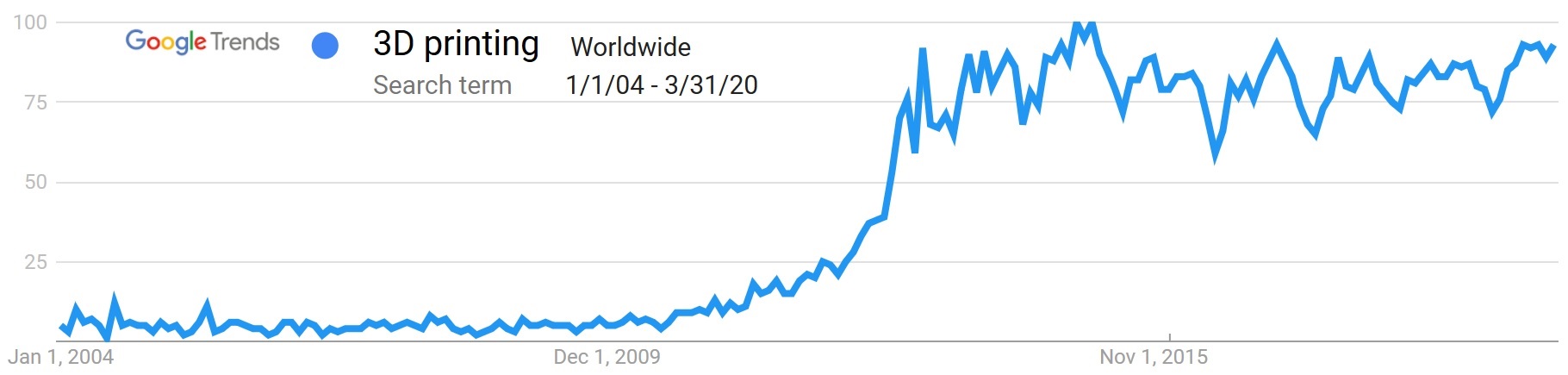 Google Trends on 3D printing
As time went on, my personal and business interests shifted away from technology and I turned my focus to other important issues in the world. After 25 years in the bustling Los Angeles that had kindled so many dreams in earlier days, I began to grow weary of the “big city.” In 2016, I went to my storage unit, resolved to let go of a lifetime of accumulated stuff. But some items were just too special for a yard sale or Goodwill. I took some pictures and made up a webpage that I sent around to some friends, asking who might be interested. One of the sections of that page was 3D Printer Relics (1990s) and had three photographs of some treasured items saved from my career in fabbers (but using the term that people these days know them by). With no takers among my friends, there was no way I could just toss those things out, so I lugged home all the fabber-related boxes and set about making photographs of every single item, then put up a new website putting it all on display and offering it for acquisition. For this, I sent notice to my old contacts in the “rapid prototyping” industry, as well as leading organizations in the “3D printer” field that had grown out of it.
After two months and talking with dozens of people, I got a referral from a curator at the Charles Babbage Institute, a leading computer museum, to Arthur Fournier, a New York dealer in “materials related to the transformative cultural movements of the late 20th century, modern conflicts, disruptive technologies, music and the visual arts.” Not only did Fournier take an interest, he also taught me to understand the value of related materials in my personal files and on my computer, which expanded the collection from its original five sections to eight. Fournier did an incredible amount of research before taking me on as a client, including flying out to Los Angeles to see for himself what I had.
Fournier put together a beautiful offering catalog, which he shopped discretely to the museum curators in his Rolodex. A few of the places he talked with were famous enough to get me excited, such as the Smithsonian and the Science Museum of London, which has on display James Watt’s original steam engine. Although his compensation would be by commission, Fournier was committed to finding the best home for the materials, which he considered to be (with no disagreement from me) of historical importance. In the end, we narrowed the negotiations to Pennsylvania State University. I had known some of its faculty for their research in the field in the 1990s, but had not known about the powerhouse they’d built up in the meantime on 3D printer education and research. As I told the Penn State curators when we inked our deal, I felt like I was sending my baby off to college, and I trusted them to take good care of it. In early 2018, Fournier and I converged back in Los Angeles to spend a day together packing boxes to museum standards, turning over 23 boxes weighing 490 pounds to Federal Express for shipment to Pennsylvania.
I don’t envy Penn State for the task they had of curating the more that 20,000 physical and digital items shipped to them that day. I’m excited to see that they have now finished organizing it all into their archival system and posted their finding aid to make it available to the university and the public.
I started Ennex Fabrication in 1991 with a vision of “fabbing the future.” But I was also enough of a packrat to pay attention to preserving the past. I’m glad those two aspects of my career combined to create something to allow future generations (if there are any) to get a glimpse of where their home fabbers came from.
Related materials:
- Ennex 3D Printing Archive Acquired by Penn State: News release announcing the availability of the Fabbers Archive at Pennsylvania State University, May 2020.
- The Fabbers Archive: Guide to online materials about the archive on Ennex.com.
- Guide to Ennex Corporation records, 1991-2005: The official finding aid for the archive at Pennsylvania State University.
- Acknowledgments: Ennex thanks many of the most important people who contributed to our work throughout the 1990s.
This project story was updated in May 2020 from the original version written in 2003.
Read about other Ennex projects.
Footnote
* In 2018, Ennex underwent a corporate reorganization, in which the name of Ennex Corporation changed to Ennex Research Corporation.